New, Extended Capabilities of PASS/Nozzle-FEM
Authors: Roman Unesikhin, Andrey Krasnokutsky, Ph.D., and Alexey Timoshkin, PASS SUITE team
What is PASS/Nozzle-FEM
PASS/Nozzle-FEM is a program designed to calculate the stresses and flexibility of nozzle-to-shell junctions using the finite element method (FEM). It also calculates the nozzle’s allowable loads and estimates the strength of the junctions for a wide range of geometric configurations and operating conditions. The program helps engineers to provide higher levels of equipment safety while reducing labor costs at the design stage. It is intended for use by equipment and piping designers and mechanical engineers and can help them to quickly check and satisfy requirements for loads on pressure vessel/equipment nozzles, as well as on non-standard piping fittings. It is recommended for use in design and industrial safety reviews in oil and gas, refineries, petrochemical, chemical, power, and other industrial facilities.
It can also calculate the SIF and k-factors for tees that are not covered by ASME B31 codes such as lateral tees and tees with D/T>100.
Unlike other widely available FEM programs (eg. ANSYS, NASTRAN, etc.), PASS/Nozzle-FEM does not require special training and can be used by any mechanical engineer. It automatically creates the FE mesh and estimates the calculation results. The use of FEM calculations as opposed to semi-analytic methods (i.e. WRC 107(537)/297) expands the application range of the program and increases the accuracy of its analyses.
PASS/Nozzle-FEM performs stress analysis fоr nozzle junctions of different types (including trunnions) connected to cylindrical, conical and flat shells, as well as for cone, elliptic, hemispherical, torispherical and flat heads. It takes into account the vessel boundary restraints and loads on the nozzle from the adjacent pipeline. It can calculate nozzle and shell membrane, bending and total stresses. It can also calculate the pipe branch connections to enable a detailed stress analysis of non-standard tees and stub-ins. The new feature of the program allows to analyze cylindrical and conical skirt supports of column vessels.
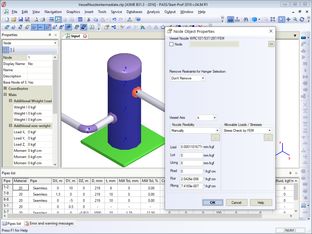
In addition to stress and stability analysis, the program also performs nozzle-to-shell junction flexibility calculations since this flexibility can considerably influence the vessel and piping stresses. During a stress analysis of pipeline systems, nozzle-vessel junctions are often simulated by anchor supports which leads to an overestimation of stresses and tensions. To address this and automatically create appropriate non-standard support in the calculation model, the program allows engineers to pass the nozzle-shell junction flexibilities calculated by PASS/Nozzle-FEM into the PASS/START-PROF piping stress analysis program.
The program allows stress estimation using different codes for allowable stresses, including:
- ASME VIII div.1, 2;
- EN 13445-3;
- JB 4732-1995;
- GOST 34233;
- PNAE G-7-002-86.
It supports vessel stress and stability analyses and the reinforcement required of openings under internal pressure. The program also analyzes nozzle-shell junctions operating in corrosive hydrogen sulphide environments.
Have a look the PASS/Nozzle-FEM Overview Webinar recording:
Major Changes to the Program Kernel
In 2018-2020 years, PSRE Co released Nozzle-FEM versions 2.15, 2.16, 3.0 and 3.1, which introduced several major changes. The company completely reworked the program kernel and user interface, to improve the program’s usability, speed, extensibility, support for hierarchical models at the logical level, and much more.
The program kernel consists of three main components (Fig. 1), which can be used independently of each other. The object-hierarchical model is intended to be managed by the user, and presents an analysed structure as a tree of objects: for instance, the nozzle is represented as a child object of the supporting shell. In this model, only those geometric data that describe the object itself, and the data required for positioning the child objects are specified.
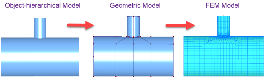
A geometric model, which is a topological model, so it contains information about curves, surfaces, solids, and the relationships between them, is generated from the object-hierarchy model. This program component uses a licensed C3D geometric kernel. Currently, a shell-based topological model is used in the Nozzle-FEM kernel, which is built along the middle surface of the shells.
A FE model that consists of the shell’s finite elements is then built based on the geometric model. A system of linear algebraic equations corresponding to the equilibrium conditions of the solid is compiled for the FE model.
Refined Calculation Methods
Version 2.15 also refines the following basic
calculation methods: strength, allowable loads on the nozzle, stiffness, and
stress intensification coefficients.
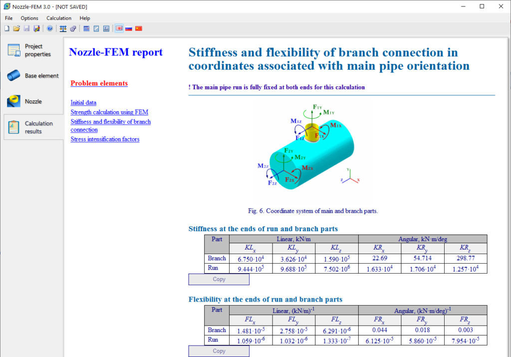
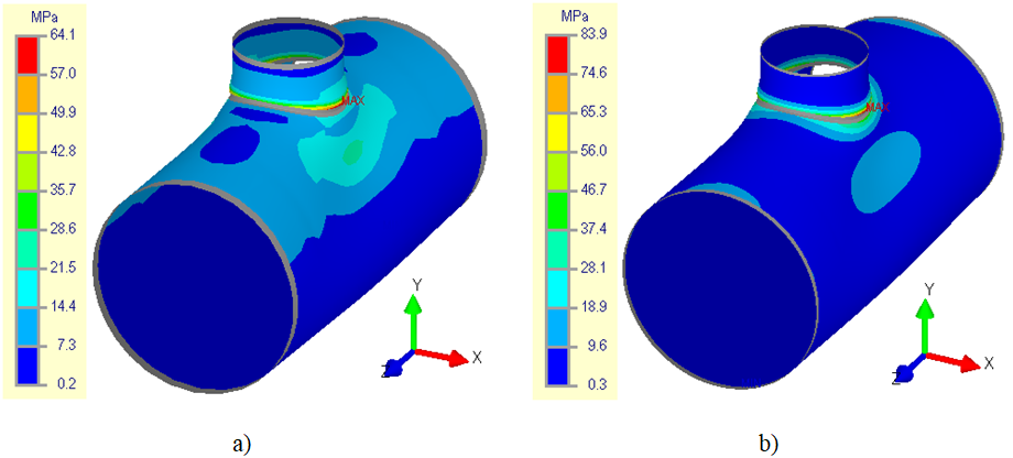
Two approaches are now used in stiffness (flexibility) calculations: stiffness calculations of the “Supporting shell – nozzle” system (total stiffness), and calculations of stiffness excluding the beam (local stiffness at the place of the nozzle’s tie-in). This second approach is applied for simultaneous work with programs which use a beam FE model (such as PASS/START-PROF) and some equipment modeling (such as vessel shell or tee in PASS/START-PROF). In this case, PASS/Nozzle-FEM builds an equivalent beam model in background, and the local “shell” junction’s stiffness is determined by the difference between the displacements of the shell and the beam models:
where  is a calculated value of the i degrees-of-freedom at the end of the nozzle in the beam FE model, and
  is the same in the shell model.
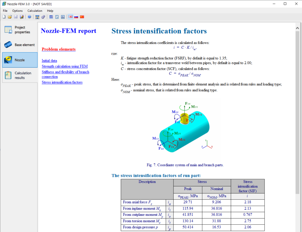
To refine the stress and strain calculation methods, a
stress extrapolation procedure was
introduced, which solves two problems:
- It allows the FE mesh to be condensed in the stress concentration zones by introducing special zones in which additional refining and alignment of the mesh is performed;
- It increases the convergence of results at different mesh refining levels, reducing design errors (and mitigating the habit of users to not use calculation checks on very fine meshes).
The stress extrapolation procedure is implemented by the Hot Spot Stress method (HSS). HSS uses a linear surface extrapolation (LSE) procedure to calculate the stress at the weld toe (Fig. 2). The selection of the points t1 and t2 by LSE depends on the shell thickness s. This approach stabilizes the process of determining stresses around concentrators and increases the convergence of the results at different mesh refinement levels in the FE model.
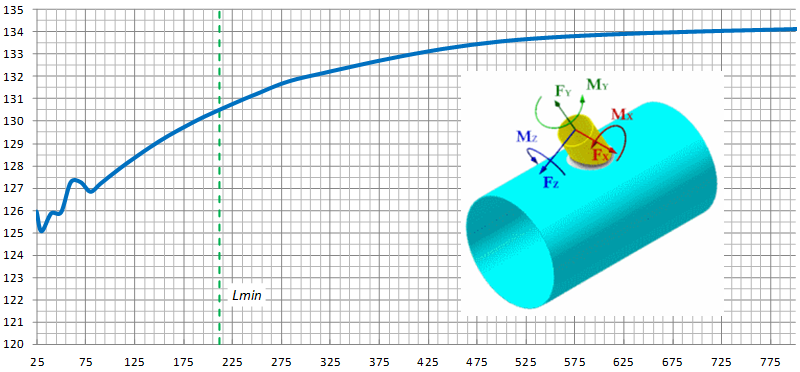
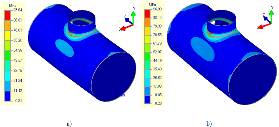
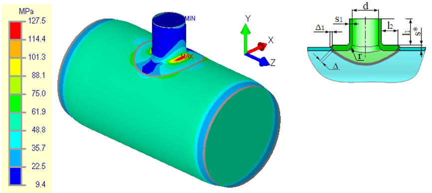
For instance, we can compare the results of calculations obtained with the extrapolation procedure and without it using the example of a nozzle tie-in to a cylindrical shell with an axial force of 100 kN applied at the nozzle. In this case, using earlier approaches, you couldn’t determine the maximum total stresses even at the 5th level of mesh refinement (Fig. 3b). The total stresses (membrane + bending) on the outside surface at the first level were 64.1 MPa (Fig. 3a); taking into consideration a mesh coefficient of Km = 1.30, the calculated stresses would be equal to 83.3 MPa. At the same time, the stresses at the fifth level of the mesh were 83.9 MPa (Fig. 3b) and, taking into account a mesh factor of Km = 1.05, the stress would be 88.1 MPa. This demonstrates that the maximum value of total stresses at the first level did not reach the value of the fifth level. The figure below shows that the maximum peak values are not obtained even at the fifth level of the mesh.
Instead, when using the stress extrapolation procedure for this same example (Fig. 4), the first and fifth levels of the mesh produce similar results which exceed the results of the calculations done without applying extrapolation of stresses.
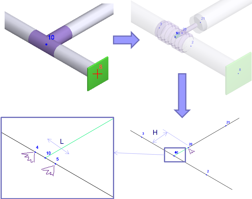
Version 2.16 of PASS/Nozzle-FEM, released in December 2018, offers a new approach to “in Junction” calculations which occasionally causes misunderstanding among users about how stresses are calculated in the welded zone. The “in Junction” option is usually used when the pipe ends at the area of junction into the shell (point “i” in Fig. 5). The pipeline calculation model usually ends on the outside surface of the shell, and calculation loads on the nozzle are obtained at this point.
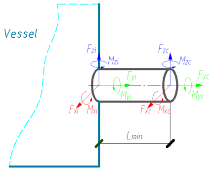
In versions before 2.16, the most minimal nozzle calculation length possible was taken to build the FE model. After version 2.16, the nozzle length is determined by the condition of sufficient flexibility:
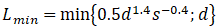
This allows engineers to consider an ovalization of the section at the junction area that corresponds to the “flexible” connection between the pipeline and the shell, and has been obtained from numerous field tests. In versions up to 2.16, when selecting “in Junction”, the minimal length taken led firstly to a more rigid junction of the pipeline into the shell and secondly to an incorrect determination of the stresses in the junction area since edge effects could occur at the load application point on the nozzle (Fig. 6).
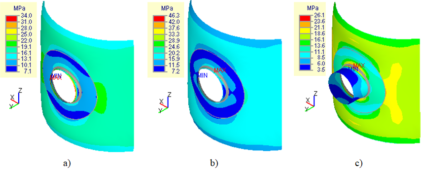
a) L=30мм – well-defined edge effect from the load application;
a) L=50мм – short length of the nozzle, falls within the area of the edge effect of the load application;
c) At the nozzle length obtained by formula (2).
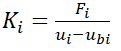
Fig. 7 represents the change curve in the allowable axial force Fy depending on the nozzle length L1, which shows that, in the junction area, at a distance less than 100 mm, edge effects from the load application point appear. Calculation results are given for a tilted nozzle with an inside diameter of 203 mm and 6 mm thickness joining into a cylindrical shell with an inside diameter of 2000 mm and a thickness of 12 mm (Fig. 7).
When calculating the strength, the PASS/Nozzle-FEM software automatically converts the loads specified by the user at the junction point into statically equivalent loads, corresponding to a section with a length L1 = Lmin (Fig. 5).
New Types of Nozzle Junctions
The reworking of the kernel, and the use of the up-to-date C3D geometric kernel for solid modelling has enabled the inclusion of several new types of junctions with beading and weld-in toroidal insertions (Fig. 8). Users can therefore now model stamped and stamp-welded nozzles using PASS/Nozzle-FEM program.
New Bearing Elements
Unlike with PASS/EQUIP, PASS/Nozzle-FEM did not offer a conical transition with the displacement of the second end (eccentric transition) for a long time due to difficulties associated with the complexity of its implementation within the program’s old kernel (Fig. 9).
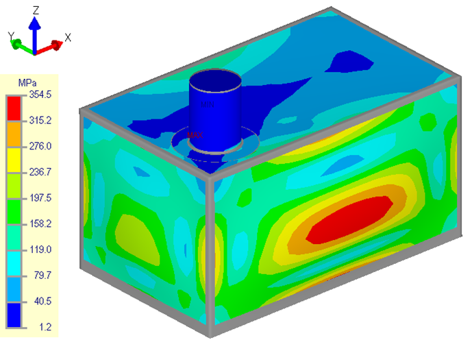
Many users also asked for the addition of flat rectangular covers to the program, with which it is possible to model junctions into air-cooled heat exchanger (ACHE) covers, walls of cubic vessels, etc. These elements have now been added to the list of calculation models (Fig. 10).
Loads
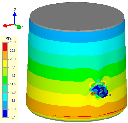
In order to simulate real loads more correctly, an option has been added to set the hydrostatic pressure required for calculations of vertical vessels and tanks, although this load can be set for other types of shells (Fig. 11). Hydrostatic pressure now changes linearly along the vertical axis, where the maximum value is determined at the level of the model’s lowest point. For vertical vessels (tanks), this corresponds to the level of the head.
Thermal strain was another popular and fundamental addition to version 2.16 of the program. This allowed the expansion (deformation) of materials in the structure elements to be considered under the effects of temperature, as well as any additional stresses arising from constrained temperature deformations (different linear expansion coefficients, temperatures, etc.).
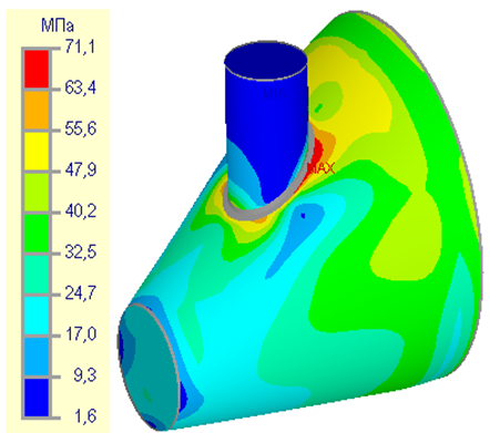
Fig. 12a shows the distribution of equivalent stresses in an elliptical head with an internal pressure of 0.5 MPa. The maximum stress value was 86.6 MPa. As an example, the materials on the shell and nozzle were set at different linear thermal expansion coefficients, with different temperatures on the head (200 °С) and on the nozzle (220 °С). This will generate a temperature deformation constraint and junction stresses will drastically increase (Fig. 12b) in the area of the nozzle, to a maximum stress value of 118.5 MPa.
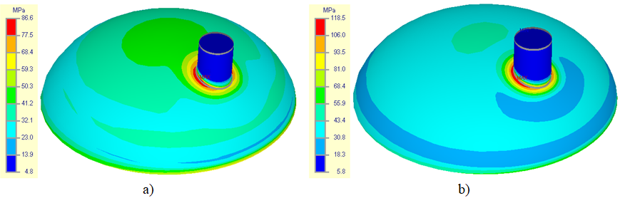
a) internal pressure; b) internal pressure and temperature
The ability to consider the effects of temperature has also enabled better compliance with regulatory requirements. For instance, with ASME BPVC.VIII.2, the thermal expansion of materials should be considered when checking the equivalent stresses of the “Secondary Membrane plus Membrane” category. In GOST 34233.1-2017, while checking with formula (12), it is necessary to consider the additional stresses arising from the effect of temperature:

or while calculating temperatures with formula (13), at which the allowable stresses are defined by the limits of long-term strength or creep:

The capability to set several load cases in single project and run the analysis for all load cases at once was added in version 3.0. Starting from version 3.1 the program can also make analysis for testing and mounting conditions for all codes/rules.
Code Updates
In the development and refinement of the new version of the kernel, a module for strength verification in accordance with various regulatory documents was also reworked, which provides quite flexible and fast processing of updated versions of different codes. As a result, the program is now compliant with
- ASME BPVC.VIII.1, 2‑2017,
- EN 13445‑3:2014 (E) Issue 4 (2017‑07),
- GOST 342233.1, 6, 10-2017.
Roadmap
With regard to the future, the PASS team envisions PASS/Nozzle-FEM as an interactive builder of pressure vessels on the one hand, and as a possible embedded solution to “seamlessly” integrate with the PASS/EQUIP and PASS/START-PROF programs to calculate junctions and tees directly in their environment.
Another possibility is that two software solutions will be available simultaneously: a separate program with advanced options for creating complex models, and an equivalent to the current version with the option of embedding it in the other software. Both will be more functional and interactive than they are now.