Modeling Fired Heater Piping Connection is a bit tricky as the pipe is not welded to a fired heater shell similar to ordinary equipment. The heater has a hole, the pipe runs through that hole inside the heater body.
There are two techniques for modeling fired heater piping connection:
First method: Use an anchor at the point where the piping goes inside the heater. The heater vendor must provide the allowable loads for this anchor point. Or the API 560 code may be used
Second Method: Model whole or part of the furnace coil that is inside the heater. The vendor should provide allowable displacements at the point where the pipe goes inside the heater (+dx, -dx, +dy, -dy, +dz, -dz). Usually, it’s the gap values between the pipe and heater shell
You can choose one of these two methods.
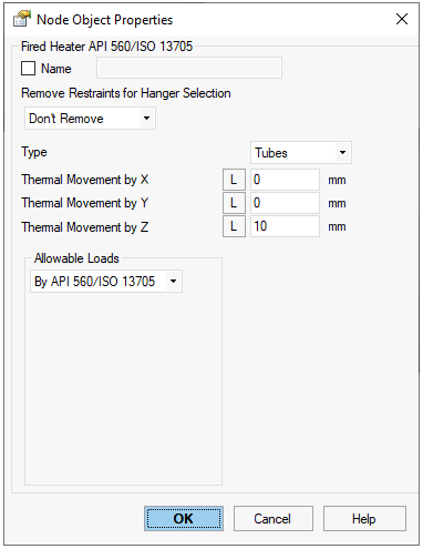
First Method – Allowable Loads
First method is very conservative. The loads on heater usually are very huge, but allowable loads are very small and can’t be met.
In START-PROF software the “Fired Heater” Object can be used.
Allowable Nozzle Loading Method of Fired Heater Piping Connection Model
Second Method – Allowable Displacements
Using the second method it is more easy to satisfy the vendor requirements. There’s no need to model whole furnace coil, just 3-4 U-Tubes is enough.
Allowable displacement model of Fired Heater Piping Connection model
The supports in the furnace coil should be modeled correctly.
The following conditions should be met:
Pipe displacements at the point where pipe hoes inside the heater should be less than vendor’s allowable
All stresses both in the pipe and in the furnace coil should be less than allowable according to the selected code
Loads on the furnace coil supports should be less than allowable