Video: How To set Shell and Nozzle Parameters in Nozzle FEM
Unlike the universal FEM programs (ANSYS, NASTRAN, COSMOS, etc.), this program does not require special training and can be used by any mechanical engineer. The creation of finite element mesh and estimation of calculation results are performed automatically. FEM calculation, as opposed to semi-analytic methods (i.e. WRC 107/297, GOST 34233.3-2007, etc.), expands the program application range and increases analysis accuracy.
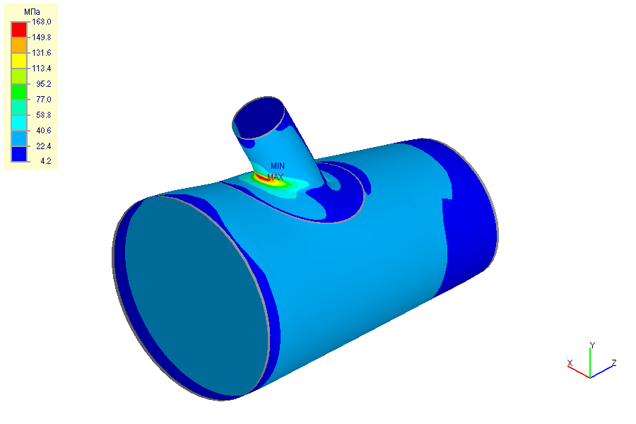
The program performs stress analysis for nozzles (including trunnions) of arbitrary geometry connected to cylindrical and conical shells, as well as elliptic, hemispherical and flatheads. It takes into account vessel boundary restraints and loads on the nozzle from the adjacent pipeline. Both nozzle and shell membrane, bending and total stresses can be calculated. Calculation of the pipe branch connections is also implemented, enabling detailed stress analysis of non-standard tees and pipeline branch connections.
Along with stress and stability analysis, the program also performs nozzle-shell junction flexibility calculation, as this flexibility can considerably influence vessel and piping stresses. During stress analysis of pipeline systems, nozzle-vessel junctions are often simulated by anchor supports which leads to an overestimation of stresses and tensions. In order to automatically create the appropriate non-standard support in the calculation model, the nozzle-shell junction flexibility calculated by Nozzle-FEM can be copied via the clipboard into the PASS/START-PROF piping stress analysis program.
Stress state can be estimated by different codes: ASME VIII div.1,2; EN 13445-3; GOST 34233.1-2007; JB 4732-1995; PNAE G-7-002-86 (for equipment and pipelines of nuclear power plants) for allowable stresses. Vessel stress and stability analysis (according to GOST 34233.2-2007) are also implemented, as well as reinforcement required of openings under internal pressure (GOST R 52857.3-2007). Nozzle-shell junctions working in a corrosive hydrogen sulfide environment are analyzed in accordance with GOST 34233.10-2007.
Besides finite element method calculation, the program supports CIF and flexibility calculation via semi-analytic methods according to WRC107-79, WRC297-87 (Welding Research Council Bulletins No. 107, No. 297 “Local stresses in spherical and cylindrical casings caused by the external loads”) and BS5500-76 (British standard).
The calculation results can be automatically reported in RTF.
In this Video-series created by PASS distributor in Australia – Moonish Engineering Setting of Shell and Nozzle Parameters will be explained.